
Key takeaways
- Treat startup inrush and normal operating load as separate electrical design inputs.
- Request the exact driver model, input range, inrush waveform or stated value, duration, repetition and test conditions where available.
- Do not calculate a universal number of LED drivers per circuit from wattage alone.
- Check switching devices, protective devices, wiring, control strategy and ambient conditions as one installation system.
- Use a qualified electrical designer to approve the final circuit, protection and commissioning method.
1. What is LED driver inrush current?
LED driver inrush current is the short-duration input current that can occur when a driver is energized. It is different from the driver's steady-state input current after the power stage has started. A commercial lighting circuit can therefore behave differently at switch-on than it does during normal operation.
The practical buyer task is to make the two conditions visible in the same schedule. Inrush information helps the electrical designer assess switching and protective-device behavior; it does not replace the driver's rated input, output, load and environmental requirements.
The value and waveform depend on the exact driver design, input condition, switching timing, upstream impedance, temperature, connected load and measurement method. A generic internet figure is not a substitute for current model documentation.
| Electrical input | What it answers | What it does not prove |
|---|---|---|
| Steady-state input | Expected operating load after startup | Startup switching behavior |
| Inrush current | Short-duration energization demand | Long-term energy use or driver capacity |
| Output rating | The connected LED load boundary | Compatibility with every strip or luminaire |
| Protection data | A device's stated operating or coordination basis | Approval of an entire building circuit |
| Measurement record | Observed behavior under defined conditions | Performance under another model or installation |
2. Collect the exact driver data before planning a circuit
Start with the precise driver or power-supply model and revision proposed for the project. Record input voltage and frequency range, rated input power or current, output method, output voltage or current, rated load, control interface and the manufacturer's stated inrush information if supplied.
Ask how the inrush value was defined: peak or RMS, source impedance, ambient condition, switching phase, test duration, repetition and whether the measurement represents one driver or a connected group. If the document does not state the basis, mark the item as pending rather than converting it into a precise design number.
Keep product data separate from a site measurement. The same model can be installed under different upstream conditions, cable lengths, switching devices and grouping arrangements.
- Exact driver model and revision
- Input voltage, frequency and phase arrangement
- Rated input current or power basis
- Stated inrush value, duration and test conditions
- Output voltage or current and permitted load range
- Dimming, relay, contactor or control interface
- Document owner, issue date and unresolved questions
3. Separate normal load from startup coordination
Use the steady-state load to understand normal operation, thermal loading and energy demand. Use inrush information to prompt review of the switching and protection arrangement at energization. These are related but different checks and should remain separate rows in the electrical schedule.
For a group of drivers, record how many units can energize together, whether a controller stages the start, whether circuits are switched by a relay or contactor, and whether the design includes a defined delay or sequence. Do not assume that staggering is available or effective without checking the actual control system and commissioning behavior.
A driver with a lower wattage can still require a separate inrush review. Conversely, a larger rated driver is not automatically a solution to a switching or protection mismatch.
| Schedule row | Record | Review question |
|---|---|---|
| Operating load | Driver count, input basis and connected load | Does normal demand fit the circuit and supply? |
| Startup group | Units energized together and switching sequence | What happens at simultaneous energization? |
| Control device | Relay, contactor, dimmer, controller or BMS interface | Is the device rated for the defined load and event? |
| Protection | Selected device and designer's coordination basis | Has a qualified person reviewed nuisance tripping and safety? |
| Verification | Commissioning condition and observed result | Was the approved sequence checked on site? |
4. Why wattage alone cannot determine driver count
Wattage is useful for a first estimate of steady-state demand, but it does not describe peak startup current, waveform, duration, power factor, control behavior, upstream impedance or protective-device coordination. Dividing a circuit rating by driver wattage can therefore produce a misleading release rule.
The final number of drivers on a circuit depends on the exact equipment, supply, wiring, protection, switching device, installation environment and applicable local design requirements. A supplier can provide product data and a proposed schedule; the project electrical designer remains responsible for the circuit decision.
If a quotation asks for a driver quantity per circuit, return the assumptions with it: exact model, input condition, simultaneous-start group, switching device, protection basis and whether a staged sequence is required.
- Do not divide only by nominal watts
- Do not copy a count from another driver family
- Do not treat a successful one-unit power-on as group coordination proof
- Do not infer protection settings from a product photograph
- Do document the design assumptions and responsible approver
5. Check switches, relays and controls at the same time
The switching device is part of the inrush review. Check whether a wall switch, relay, contactor, dimmer, smart controller or building-management interface is intended to energize one driver, a zone or a full installation group. Its electrical rating and control method must be reviewed against the actual driver behavior and local design requirements.
Record whether switching is direct, staged, scene-based or controlled by a timer. If the system has a recovery sequence after a power interruption, include that event in commissioning. Do not describe a controller as an inrush limiter unless the manufacturer documentation and installed configuration support that function.
Keep control compatibility separate from dimming compatibility. A driver may accept one control method while its switching, restart or low-level behavior still needs a separate check.
6. Define a qualified verification plan
Before release, agree who will review the circuit and what evidence is required. Depending on the project, the plan may include the driver's current datasheet, protection and coordination review, wiring schedule, control sequence, representative startup test and records from the responsible electrical professional.
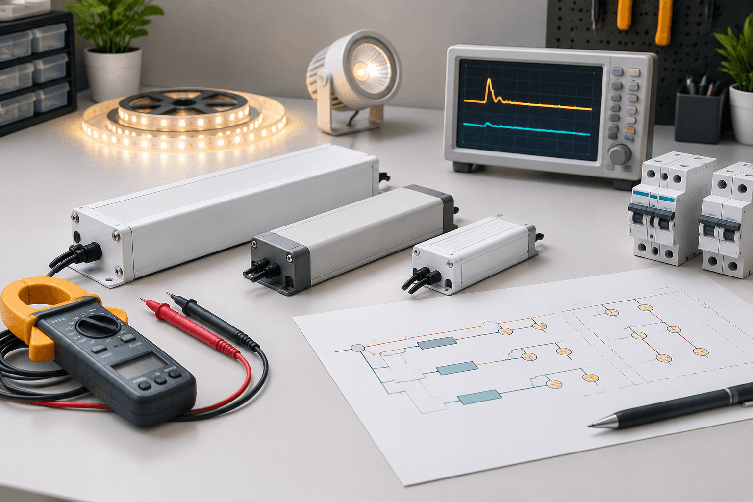
A clamp-meter reading can support an observation, but the instrument, sampling rate, location, switching event and connected group must be appropriate for a short transient. A normal handheld reading may not capture a peak inrush event. Do not present an incomplete measurement as a definitive product value.
Record the test boundary: model and revision, quantity energized, source condition, control state, ambient context, measurement method, date, observer and result. The record applies to that defined arrangement only.
| Verification item | Evidence to retain | Limit |
|---|---|---|
| Product identity | Model, revision and current data sheet | A family name is not enough |
| Circuit basis | Drawing, schedule and designer review | This article is not an electrical design |
| Control event | Switching sequence and device reference | One manual switch-on may not represent automation |
| Transient observation | Instrument, sampling and test conditions | A slow meter can miss a peak |
| Close-out | Result, exceptions, approver and date | A pass under one setup is not universal proof |
7. Buyer checklist before releasing the circuit plan
Use this checklist to keep the product quotation, electrical schedule and commissioning record aligned.
- Exact driver model, revision and quantity are frozen
- Input range, steady-state basis and output requirements are recorded
- Inrush value or pending status includes its definition and test conditions
- Simultaneous-start groups and any staged sequence are shown
- Switches, relays, contactors, dimmers and controllers are identified
- Protection and coordination have a named qualified reviewer
- Wiring, isolation, access and environmental boundaries are documented
- The verification method can capture the relevant startup event
- Exceptions, substitutions and revised driver data remain traceable
- The final circuit decision is approved for the exact project and market
Frequently asked questions
Questions buyers ask
Is LED driver inrush current the same as rated input current?
No. Rated input current usually describes an operating condition, while inrush is a short-duration energization event. Use the exact driver's documentation and keep both inputs in the circuit review.
Can I calculate how many LED drivers fit on a circuit from wattage?
Not reliably from wattage alone. The count also depends on the exact driver, startup behavior, switching device, protection, wiring, grouping and local electrical design requirements.
Does staged switching always solve LED driver inrush?
No. Staging may change the startup event, but its timing, control path, device rating and recovery behavior must be documented and verified for the actual installation.
Can a normal clamp meter measure driver inrush?
It may not capture a short peak unless its bandwidth, sampling and capture mode are suitable. Record the instrument and method, and do not treat an incomplete reading as a definitive peak value.
Who should approve the final LED circuit plan?
The project should name a qualified electrical designer or responsible professional according to local requirements and the project's governance. Supplier product data supports the review but does not replace it.
Talk to the product team
Planning an OEM or commercial lighting order?
Send your application, specification and destination market. We will help narrow the product and sample options.
Discuss on WhatsApp