
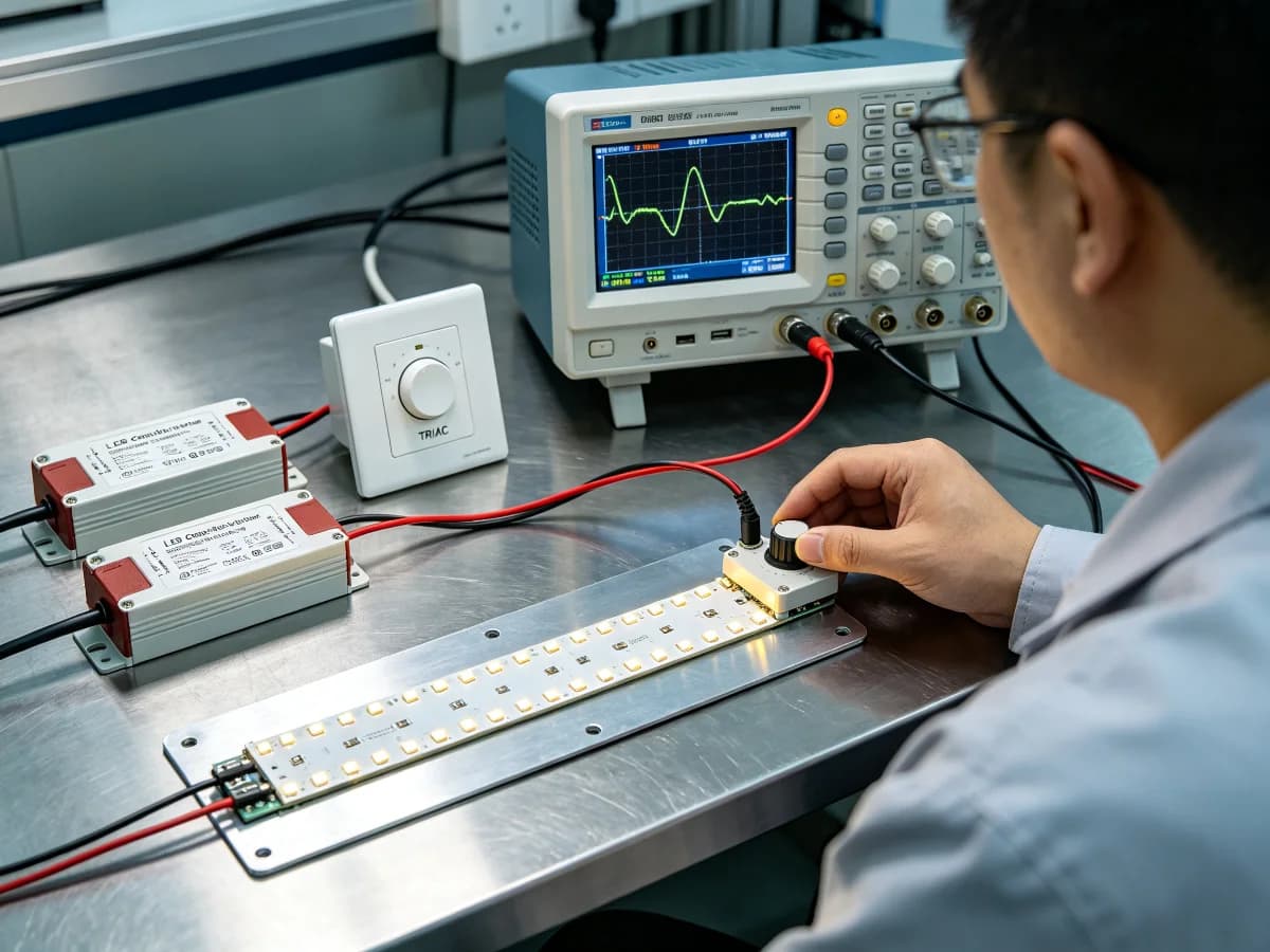
Key takeaways
- Choose the control method before approving the driver: phase-cut, 0-10 V, DALI, PWM and other systems are not interchangeable simply because every component is called dimmable.
- Match strip voltage and connected load, then verify the exact driver, dimmer or controller, wiring, control range and installation conditions.
- Test full output, normal scenes, the required low end, fades, start-up, shutdown and power recovery using the real component combination.
- Keep exact model numbers, revisions, settings and approved alternatives in one compatibility matrix.
- A representative mock-up is part of procurement evidence because behaviour can change with load, scene, fade direction, temperature or camera settings.
1. How do buyers match an LED driver and dimming control?
First define the required control method and confirm that the exact driver accepts it. Match driver output voltage to the LED strip, calculate actual connected load, and check the documented operating range and installation conditions.
Then verify the exact dimmer, controller, gateway or control system with the exact driver. Record wiring, settings, zones and manufacturer compatibility evidence. Dimmable on two separate labels does not prove that the products work together.
Finally, test the intended strip length and component combination at full output, normal use, the required low end, scene changes, start-up, shutdown and recovery after power interruption.
- Strip model, voltage, watts per metre and length
- Driver model, output and documented load range
- Dimming or control method
- Exact dimmer, controller or gateway
- Wiring, settings and zone allocation
- Mock-up conditions and acceptance criteria
2. Why must the control method be chosen first?
The control method determines what signal or electrical behaviour the driver or controller must understand. A wall-box phase-control project has a different system boundary from a 0-10 V control pair, a DALI network or an output-side PWM controller.
Do not substitute one method because products share the word dimmable. Confirm where control is applied, which device interprets it, how the load is powered and which documents cover the complete combination.
If the project needs building-management integration, scenes, individual addressing or simple local control, define that operational requirement before requesting quotations.
| Control approach | Buyer should confirm | Common approval gap |
|---|---|---|
| Phase-cut | Exact dimmer-driver compatibility, load, wiring and control direction | Assuming any phase-dimmable driver works with any wall dimmer |
| 0-10 V | Driver input, controller, control wiring, off behaviour and zone plan | Checking power wiring but omitting control wiring or off-state requirements |
| DALI | Documented devices, addressing, commissioning and system ownership | Buying drivers without assigning configuration and commissioning |
| PWM or output-side control | Controller voltage, load, channels, method and strip compatibility | Placing an unverified controller between driver and load |
| Wireless or smart control | Gateway, protocol, firmware, commissioning and fallback behaviour | Approving a demo without recording versions or recovery steps |
3. How do voltage and connected load affect compatibility?
Driver output voltage must match the LED strip system. Calculate connected load from exact installed length and product watts per metre, then check it against the driver's documented operating and dimming conditions.
A driver can have enough headline wattage and still be unsuitable for the control method, load range, environment or low-end behaviour. Installing a larger driver does not automatically improve dimming.
If branches share one driver or controller, show every branch on the load schedule. Include feeds, cable routes, connectors and control zones so the quotation reflects the installation rather than a short sample.
| Check | Record | Reason |
|---|---|---|
| Output voltage | Exact strip and driver voltage | Prevents a basic electrical mismatch |
| Connected load | Watts per metre x actual length for every branch | Defines real driver and controller load |
| Operating range | Manufacturer-stated load and environmental conditions | Headline capacity may not cover every dimming condition |
| Branch layout | Feed points, cable routes and connectors | Separates control issues from voltage drop or connections |
| Control zones | Branches that switch and dim together | Links electrical load to required scenes |
4. What low-end and scene behaviour should be approved?
Approve the project's required low scene, not the lowest number printed on a controller. Record where the light remains stable, visually acceptable and repeatable with the exact strip, driver and controls.
Test dimming down, dimming up and holding the scene. Also check branch synchronisation, colour appearance and any human-visible or application-relevant camera banding.
Define off behaviour. Some projects need a switched-off state while others use a control command with standby behaviour. The system and commissioning plan must support the stated requirement.
- Full output and normal scene
- Required lowest scene
- Fade up and fade down
- Start-up and shutdown
- Scene recall and branch response
- Power interruption and recovery
- Relevant camera behaviour
5. What belongs in a dimming compatibility matrix?
Use one row for each approved component combination. This gives purchasing, installation and maintenance teams a controlled reference and makes substitutions visible before products reach site.
Connect the strip, driver, dimmer or controller, settings, load, wiring and observed result. Record firmware or gateway versions when they can affect the system.
An alternative component needs its own row and test result. Similar ratings or the same protocol name do not make it an automatic equivalent.
| Matrix field | Record | Approval purpose |
|---|---|---|
| Load | Strip code, length, branches and watts | Reproduces the tested electrical condition |
| Driver | Model, revision, output and dimming method | Identifies the powered and controlled component |
| Control | Dimmer, controller, gateway and version or setting | Identifies how commands reach the system |
| Wiring | Diagram reference and zone | Prevents a compatible set from being wired differently |
| Observed result | Low end, fades, start-up, off state and camera check | Records what the project approved |
| Status | Approved, conditional, rejected or retest | Stops untested substitutions entering the order |
6. How should a representative mock-up be tested?
Use the intended strip and representative installed length, not only a short bench sample. Include the final driver, dimmer or controller, wiring, profile or diffuser, controls and normal enclosure or ventilation condition where practical.
Operate long enough to reveal relevant warm-up behaviour. Run repeated commands and record instability, delay, pop-on, drop-out, uneven branch response, noise or unexpected off behaviour.
Electrical work should be performed by people qualified for the project and equipment. This article does not replace product instructions, control-system design or destination-market requirements.
| Test phase | Action | Record |
|---|---|---|
| Identity | Check every model, revision and setting | Photographs and component schedule |
| Full output | Start and operate at normal maximum | Stability, output and observed noise |
| Low end | Approach from both directions and hold | Lowest approved setting and behaviour |
| Transitions | Run fades, scenes and repeated commands | Timing, consistency and branch response |
| Recovery | Follow the approved interruption test | Restart state and commissioning dependency |
| Context | Review diffuser, finishes and cameras where relevant | Visible and application-specific issues |
7. How are flicker, substitutions and repeat orders controlled?
Low-level flicker can involve interaction between driver, controller, load and configured range; it does not identify one failed component by itself. Compare an installed issue with the approved matrix and record its exact operating condition.
Freeze model numbers, revisions, settings and results in the quotation and order. A later driver, dimmer, controller or firmware substitution should trigger review and, where behaviour can change, a representative retest.
For OEM programmes, link the approved system to labels, packaging and reorder codes. Keep an alternative only after it passes the required load, wiring and scene tests.
8. What should an LED driver dimming RFQ include?
Send the complete strip, load and control requirement rather than requesting a dimmable driver alone. Ask the supplier for exact component codes, wiring, compatibility evidence and a sample plan.
Lumseq can review the destination market, strip voltage, watts and length, branches, dimming method, control zones, scenes, environment, quantity and OEM requirements before proposing components for testing.
[WHATSAPP: Discuss an LED driver dimming compatibility sample]
- Application and destination market
- Strip model, voltage, watts per metre and length
- Branch and feed layout
- Required control method
- Exact dimmer, controller, gateway or BMS interface
- Full, normal and low-end scenes
- Start-up, shutdown and recovery requirement
- Driver location and environment
- Wiring and commissioning responsibility
- Sample and acceptance plan
- Approved alternatives and repeat-order requirement
- Exact component documentation required
Frequently asked questions
Questions buyers ask
Can any dimmable LED driver work with any dimmer?
No. The control method, exact driver, dimmer or controller, connected load, wiring, settings and operating conditions must be compatible. Dimmable is not a universal interface label.
What is the difference between 0-10 V, DALI, phase-cut and PWM dimming?
They are different control approaches with different system architectures and component requirements. Choose the project method first, then use documented drivers and controllers and test the exact combination.
Why does an LED strip flicker only at low brightness?
The driver, controller, load and configured range may interact unstably there. Record exact models, load, setting and fade direction, then compare the installation with the approved matrix.
Will a larger LED driver improve dimming?
Not automatically. The driver must match voltage, connected load, control method and documented operating range. More headline wattage can leave the system incompatible or outside the tested load condition.
Should LED dimming compatibility be tested before ordering?
Yes when low-end behaviour, scenes, camera performance or substitutions matter. Test a representative load with the exact strip, driver, controls, wiring and settings, then retain the result.
Sources and references
DALI Alliance: About DALILumseq LED power supplies categoryTalk to the product team
Planning an OEM or commercial lighting order?
Send your application, specification and destination market. We will help narrow the product and sample options.
Discuss on WhatsApp