
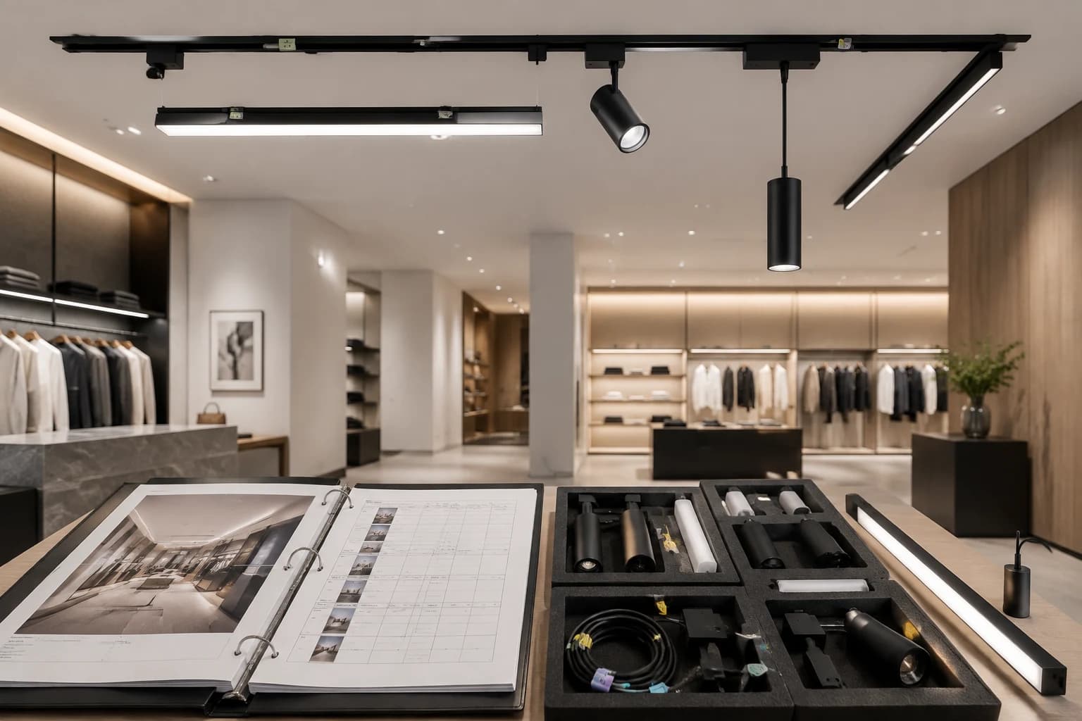
Key takeaways
- The handover pack should identify the system as installed, not only repeat the original quotation or design drawing.
- Record every track section, feed, driver, control zone and module by an exact reference that can be traced to current documentation.
- Do not assume magnetic track modules are interchangeable because they look similar; preserve the approved system identity and sample evidence.
- Test normal operation, controls, recovery and representative removal or replacement tasks before final acceptance.
- Agree which spares will be retained and who owns inspection, cleaning, fault reporting and future substitutions.
1. What should a magnetic track lighting handover include?
A magnetic track lighting handover should include the as-installed track layout, section and feed identification, driver and control records, exact module schedule, test results, spare-parts register and maintenance responsibilities. The pack must describe what was actually installed, including approved changes, rather than relying only on the tender drawing or supplier quotation.
The purpose is practical: a facilities team should be able to identify a faulted section, isolate the correct supply, verify a proposed replacement and return the system to its approved state. A collection of unlabelled product cartons or photographs is not a complete handover record.
| Handover record | What to include | Why it matters |
|---|---|---|
| As-installed plan | Track sections, joints, corners, feeds, drivers, zones and access points | Connects the ceiling layout to serviceable components |
| Module schedule | Exact reference, type, optic or CCT where applicable, quantity and installed location | Supports inspection and repeat ordering |
| Electrical record | Supply, section allocation, connected modules, driver and isolation point | Prevents load and feed assumptions |
| Control record | Zone, interface, addressing or settings, scenes and responsible party | Makes operation and recovery repeatable |
| Acceptance record | Test condition, result, deviations, date and approver | Separates verified operation from unresolved work |
| Spares and maintenance | Retained items, labels, storage, access, cleaning and replacement responsibility | Reduces ambiguity after project closeout |
2. Freeze the as-installed system identity
Start by marking the final track route and every electrical section on an as-installed drawing. Give each feed, driver, control zone and access point a durable project reference. Link those references to the exact track family, connector types and module schedule used on site.
Do not replace an exact model reference with a generic label such as ‘black magnetic spotlight’. Similar-looking tracks and modules are not automatically compatible. Track geometry, mechanical retention, conductor arrangement, voltage, polarity, driver and control method can differ. Retain the approved drawings, current technical documents and sample record that define the accepted system.
3. Build the final module, load and control schedules
Reconcile the installed module count with the approved schedule section by section. Record the exact module reference and the product fields needed for that project, such as rated input, optic, CCT, finish or control version where supported by the selected model documentation. Do not use an average wattage or transfer a field from another module family.
Update each electrical section with the installed modules, driver or supply, feeds and control allocation. Any site substitution or added module should be documented and rechecked against the applicable track, driver, feed, connector and control limits. This article does not prescribe a universal spare-capacity percentage because requirements depend on the exact system documentation.
| Schedule | Minimum project fields | Acceptance boundary |
|---|---|---|
| Module | Location, exact reference, type, quantity and approved optical fields | No visual-only substitutions |
| Load | Section, installed modules, stated load, feed and driver reference | Recalculate after changes |
| Control | Zone, interface, settings or address record and approved scenes | Names alone do not prove compatibility |
| Deviation | Original requirement, installed change, technical review and approval | Unrecorded changes remain open items |
4. Run a practical acceptance and service test
Test the system in the operating conditions the client will use. Record start-up, normal scenes, dimming or switching where specified, zone response, shutdown and recovery after isolation. Walk the installation to check that the drawing, labels and installed modules agree.
Include a representative service task when access and replaceability are important. The responsible installer can demonstrate safe isolation, access to a driver or feed, removal of an approved module and restoration of the intended scene. Follow the exact system instructions and site electrical-safety procedure; this article is not a substitute for those instructions.
- Confirm every planned track section energises and responds to the assigned control zone.
- Check module locations, aiming and optics against the final lighting intent.
- Record abnormal noise, flicker, intermittent contact, visible damage or unresolved control behaviour.
- Confirm that access panels, drivers, isolation points and removable components remain reachable.
- Attach dated results, deviations and named acceptance responsibility to the handover pack.
5. Decide the spare-parts and repeat-order strategy
A spare-parts plan should follow the installed system and the operational consequence of a failure. Record which approved modules, connectors, feeds, drivers or other service items are retained, their exact references, quantities, storage location and inspection condition. Do not invent a universal spare percentage or assume availability; agree the project quantity and confirm supply separately.
For future orders, provide the installed system reference, module code, photos of labels and engagement details, driver and control records, location, quantity and required visual result. A supplier should still verify compatibility before a substitute is accepted.
6. Final procurement and handover checklist
Close each item as accepted, accepted with a recorded deviation, document pending or not applicable. A blank field should not be treated as approval.
| Item | Closeout evidence |
|---|---|
| System identity | Track family, exact module references and current technical documents |
| As-installed layout | Sections, joints, feeds, drivers, zones, isolation and access |
| Schedules | Installed module, load, control and deviation records |
| Acceptance | Operational tests, representative service check, photos, date and approver |
| Spares | Approved references, agreed quantities, storage and condition |
| Ownership | Cleaning, inspection, fault reporting, replacement and approval responsibilities |
Frequently asked questions
Questions buyers ask
Are magnetic track light modules interchangeable?
Do not assume so. Confirm the exact track interface, retention, conductor arrangement, voltage, polarity, driver, control method and model documentation, then test the proposed module in the defined system.
What drawings are needed at magnetic track lighting handover?
Provide an as-installed layout showing track sections, joints, corners, feeds, drivers, control zones, isolation and service access, linked to the final module and electrical schedules.
How many spare magnetic track modules should a project keep?
There is no universal percentage for every project. Base the quantity on the installed module types, critical locations, maintenance strategy and agreed supply plan, and confirm availability separately.
Should magnetic track controls be tested before handover?
Yes. Test the specified switching or dimming behaviour, zones, normal scenes, shutdown and recovery, and record settings or addresses when they are part of the approved system.
Talk to the product team
Planning an OEM or commercial lighting order?
Send your application, specification and destination market. We will help narrow the product and sample options.
Discuss on WhatsApp